This page is under construction. Check back soon for complete instructions.
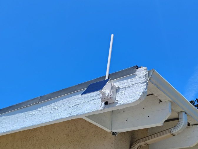
This repeater is designed to screw directly to the fascia board of a roof
edge. The antenna is in a two-foot-long tube to set it above the metal fascia
strip (metal close to the antenna adversely affects its operation.
A
fascia-mounted rooftop repeater
There are many ways to build a DIY repeater. This is how I make mine. You can
find other build instructions on the Internet
Parts List (minus antenna and mounting hardware)
1. Waterproof Box (comes with wire pass-through) 1. 3D-printed Mounting
Plate Includes Battery Holder and Radio holding tabs 1.
Heltec v4 LoRa unit 1. 3,000 MAh LiPo battery 1. 5 or 6 watt solar panel
(comes with mounting hardware) 2. M4-.70 x 6 pan head machine bolts (for
mounting plate) 3. 6-32 x 1/2 Stainless machine screws (for solar panel
mount) 3. 6-32 stainless hex nuts with nylon insert (for solar panel mount)
4. #4 x 3/8 stainless pan head sheet metal screws (for mounting plate assembly)
1. 1/2" x 1-1/2" insulating tape (to protect LoRa unit from shorting to antenna
connection) 1. JST 1.25 pigtail (soldered to solar panel wire)
Antenna
Option 1 (copper wire j-pole antenna)
1. Antenna (hand-made j-pole) 1. IPX to SMA Male with 20
mm coaxial cable (may come with LoRa unit) 1. 1/4 x 20 x
1/2 nylon pan head machine screw (for antenna mount) 1.
1/4 x 20 nulon hex nut (for antenna mount) 1. Nylon washer
(for antenna mount)
Option 2 (commercial antenna) 1. ALFA
Network AOA-915-5ACM antenna (cut to tune to 927 MHz) 1.
IPX to N Type Female with 20 mm coaxial cable
Mounting hardware
Option 1 (four bolt mount for existing pole or extension)
4.10-24 x 2-1/2 pan head stainless machine screws (for pole mounting)
4. 10-24 stainless hex nuts (to secure mounting screws to box)
4. 10-24 stainless hex nuts with nylon insert (to secure box to pole)
2. Steel reinforcements (to reinforce 3D printed pole mount adapters)
2 ft 1" PVC pipe (if using extension)
Option 2: (two bolt mount for extension)
2. 1/4 x 20 x 2-1/2 machine screws (for pole mounting) 2.
1/4 x 20 stainless hex nuts with nylon insert (to secure box to pole)
2 ft 1" PVC pipe
Antenna
Option 1
Make a j-pole antenna
Parts
1 310mm of #10 solid copper wire 1 SMA male connector on the necessary
length of RG316 coaxial cable
Construction
Bend the wire into a J shape with the short end a bit longer than 78 mm
in length. The long end should be a little more than 233 mm in length and
the elements should be 7 mm apart.
Strip the coax for about 9 mm (1/2 inch).
Unbraid the shielding and twist it together.
Strip the center conducor leaving about 2 mm (3/32 inch) of insulation.
Twist the wires of the center conductor together.
Tin both wires.
Bend the wires apart so that the coax and the stripped and tinned wires
form a T shape.
Solder the center conductor to the long element 8 mm from the bottom
of the J keeping the exposed wire as short as practiceable.
Solder the shielding to the short element 8 mm from the bottom of the
J.
Clip off the excess of both wires.
Tune the antenna for best performance.
If you don't have a nano VNA, clip the long element to 233 mm and the
short element to 78 mm
If you have a nano VNA, foll the instructions and clip the long element
about one or two mm at a time until you get the lowest SWR.
If you are putting the antenna inside a PVC pipe, check the SWR with
the antenna in the pipe.
You can adjust the bandwidth and the minimum SWR by
slightly bending the short element toward or away from the long
element.
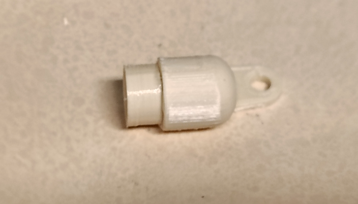
Make the parts from a material that can withstand the outdoor
environment. I use PETG but ASA is considered better for outdoor use.
3D-printed
parts for the antenna housing.
Assemble the side mount.
To simplify the 3D printing process, the side mount comes in two
parts. Assemble them with a suitable adhesive (Gorilla Glue, E6000,
Goop, Shoe Goo, etc.).
Apply glue
to the side mount insert.
Assemble
the Side Mount.
Assembled
Side Mount.
Insert the antenna into the PVC pipe.
Thread the antenna connector and coaxial cable through the hole in the
side mount.
The illustration below shows
the antenna already attached to the repeater enclosure. You can assemble
the antenna either before or after attaching the mounting hardware to
the enclosure.
Antenna
Wire Threaded Through Side Mount
Glue the PVC pipe to the Side Mount and insert the End Cap
with glue.
Finished
repeater showing assembled antenna
Once the antenna is attached to the enclosure, insert the antenna wire into
the enclosure as shown.
Option 2
Use off-the-shelf parts
I don't have an exact procedure here because I have
never built the antenna with off the shelf part. You will have to use your
judgement. You will need:
Two feet of 1/2" PVC pipe
Two PVC end caps for the above pipe.
Two brackets to mount the antenna to the repeater enclosure.
The general procedure is as follows:
Drill a 3/8 inch hole in one of the end caps.
Feed the antenna cable through the end cap as shown with the side mount
above
Make a bushing to fill the gap where the antenna cable feeds through the
end cap.
Use your chosen mounting hardware to mount the enclosure to the
weatherproff box
Be sure to waterproof any place
where the box's integrety is breeched, such as the mounting holes for
the antenna.
Making the weatherproof enclosure
Drill the necessary holes
Side hole
location.
Pilot
drilling keeps the larger bit from wandering when you start the hole.
Side hole
drilled
Top hole
location
Top hole
drilled
Bottom
hole location
Drilling
the bottom hole using a 3/4-inch spade bit.
Bottom
hole drilled.
Enlarging
the bottom hole with a rotary rasp. The hole needs to be 20 mm in
diameter.
Bottom
hole enlarged to 20 mm.
Cable
Gland mounted in bottom hole.
Now it's time to mount the antenna to the box. The following illustrations
show the antenn enclosure being built in place. You can build the antenn
enclosure and insert the antenna on separately or during the build. Be sure to
leave enough antenna cable outside the antenna enclosure to make a loose drip
loop. See the antenna enclosure building procedure.
Antenna
mounting bolts (#10-24x1/2) and nuts.(#10).
Put some
glue under the bolt heads to waterproff them.
Mount the antenna mounting hardware. When tightening the bolts, turn the
nuts, not the bolts. This keeps the waterproffing glue under the bolt heads from
twisting.
Antenna
mounts in place
Prepare the wiring for the solar panel. Cut the cable with enough length to
loop down and back up through the wire gland. You need enough cable to make a
drip loop.
Cut the
solar panel cable about where the red arrow is pointing.
Strip the wires back enoug to put heat shrink tubing on before soldering. Be
sure to identify the positive and negative wires. They are usually red and
black, but these are white and clear. Use a voltmeter if necessary.
Strip the
solar panel wires. Be sure to identify the positive and negative wires.
Put a short piece of heat shrink tubing on each wire then solder them to the
wires of one of the battery connector that came with the Heltec v4. Watch the
polarity.
Solder the
solar panel wires to one of the battery connectors.
After soldering the wires, slip the heat shrink tubing over the connections
and shrink it with a heat gun or other proper tool
The heat
shrink tubing has been placed over the soldered wires and shrunk.
Align the solar panel mount base on the box door. Use a square to make a
straight line across the door to align the two top mounting holes. Different
panels have different sized bases, so aligning the holes for each one is a
custom job
Align the
solar panel mount base and mark where the holes are to go.
Drill three 9/64 holes where the holes of the solar panel mount base will go.
Drill
holes for the solar panel mount base.
You will
need three #6-32 x 1/2" bolts and three nylon insert lock washers.
Put glue
on the face of each nut to waterproof the mounting.
Mount the solar panel on the box. When tightening the bolts, turn the bolts,
not the nut, so you don't twist the glue.
Mount the
solar panel
The wire gland that comes with the box has an inside diameter that is too
large. I make a bushing to reduce the size from a short piece of rubber fuel
hose.
I use a
short piece of fuel hose for a bushing
You need
to cut a gap in the fuel hose to slip it around the wires.
The gap should be about 3/16 inch wide.
Wire Gland
Parts Placement. The outer bushing comes with the box.
Wire gland
parts in place
Don't
overtighten the wire gland cap nut. It will push the bushing out the
other side of the wire gland.
I pack the wire gland with silicone dielectric grease—readily availale in
auto parts stores, home improement stores, etc.—on the inside to insure that
water doesn't enter around the imperfect fit of the bushing.
Coming Soon! Pole mounting the repeater
Detailed instructions coming soon, but here are the model files for the
brackets to mount this repeater on a pole. Their use should be self-explanatory.
You will need four stainless 2-1/2 inch-long #10 or 1/4-20 bolts with matching
nuts. The brackets are for a 1-3/8 inch diameter pole but should work for a
thinner pole or be modified for a thicker pole.